
Part 3: Transmittal format binary encoding
The abstract transmittal format is the standard interchange mechanism for transmittals as defined in part 2 of ISO/IEC 18023. The abstract transmittal format is realized by specifying an encoding that maps the elements of the abstract transmittal format into specific elements in one or more files. This part of ISO/IEC 18023 defines a binary encoding that conforms to the abstract transmittal format. The name of this binary encoding is SEDRIS Transmittal Format (STF).
See Table 4.1 for the table of contents for this clause.
|
4.1 Introduction and table of contents 4.3.3.1 STF object file structure 4.3.3.3 Object data and object referencing 4.3.4.2 Data table data storage |
STF provides an efficient platform independent interchange mechanism for transmittals. STF is a file format that defines the syntax of a binary-encoded transmittal.
A transmittal encoded using the techniques defined in this part of ISO/IEC 18023 consists of a set of files that together are termed an STF-encoded transmittal. An STF-encoded transmittal shall contain:
Each of these is described below.
An STF root file contains information that pertains to the entire transmittal and also information used to implement inter-transmittal reference (ITR) and non-ITR object references. It has the general structure shown in Figure 4.1:
|
Master file table |
|
ITR referenced transmittal table |
|
ITR referenced object table |
|
Published object table |
Figure 4.1 — STF root file structure
The root tile header contains transmittal level information and fields to validate and identify the STF format and version of the transmittal.
The master file table lists all of the data files that comprise this transmittal.
ITR referenced transmittal table is a list of the names of all transmittals referenced from this transmittal.
ITR referenced object table contains an entry for every ITR reference within this transmittal. Each entry identifies the transmittal and published name of the object being referenced.
Published object table is a list of objects in the transmittal that may be referenced from other transmittals.
The exact form for each element in the STF root file is specified in 6.3.1 Root file content organization.
The STF object files contain all of the DRM objects in the transmittal including field data and relationships. Each STF object file has the structure depicted in Figure 4.2:
Figure 4.2 — STF object file structure
The file header contains fields to validate the STF format and identify the version of the data. It also contains organizational information.
Following the file header are from one to 4096 STF blocks as described in 4.3.3.2 STF block.
The referenced file table is a list of the STF object files and STF ImgDTData files that contain an object that is referenced from an object within this file.
The block table data consists of two tables containing information on the sizes, location and compression of each STF block in the file.
Each STF object file contains up to 4096 STF blocks. Each block is then used to store and organize up to 256 STF objects that represent DRM objects in the transmittal. Each DRM object is given an index from 0 to 255 to locate it within the block. The layout of the block is depicted in Figure 4.3:
Figure 4.3 — STF block layout
Block header specifies the number of objects in the block and the location of the object pointer table in the block.
The object type table specifies the DRM class of each object in the block.
Object data contains object-specific data for each object as described in 4.3.3.3 Object data and object referencing.
The object pointer table specifies the location of each object in the block. It also indicates which objects have been deleted from the transmittal.
STF object data consists of the association, component, and aggregation relationships for the object as well as any DRM field data. The format of STF object data is defined in 6.2 DRM object syntax and encoding. The relationship information is implemented by storing lists of object references. Since the aggregation (parent to child) relationship is always a two-way relationship, STF stores each object’s parents and children separately. The parents are stored as aggregate object references, the children as component object references and the associated objects as associate object references.
To implement these object references, STF uniquely identifies every object in the transmittal. STF uses a set of three zero-based indices for this purpose. Every object has a reference called an FBO that is comprised of a File index (F), a Block index (B), and an Object index (O). The file index is the index into the STF root file’s master file table. This table specifies in which file the object is located. The block index is the index into the file’s block table that specifies in which block the object is located within the file identified by F. The object index identifies the specific object within the block identified by B.
The encoding of an FBO for referencing objects from other objects shall be as described in 6.2.8 Encoding of object reference lists. The encoding of items in the published object table and for the reference to the root object in the root object file header shall be as defined in 5.2.6.4 STF_FBO.
DRM_Image and DRM_Data_Table objects have non-field data associated with the object. Such data is stored in the STF ImgDTData files.
The STF ImgDTData Files are structurally identical to the STF object files with the exception of the object data for the individual objects. An STF ImgDTData file has a file header, reference file table and block table of the same format as the STF object file (see 4.3.3 STF object file). The format of the block header, object type table and object pointer table is also the same. However, the object types are limited to one of only four types of objects:
The format of these objects is defined in 6.3.4 STF ImgDTData files.
These image and data table objects also use the same FBO object referencing mechanism. A component object reference from a DRM_Image object to an IMAGE_DATA object is used to locate the image data for the DRM_Image. DRM_Data_Table objects have component object references to DT_DATA objects. While STF considers these components, they do not represent component relationships as defined in the DRM.
A DRM_Data_Table is an n-dimensional table of cells. Each cell may contain any number of elements. The number, size and extents of the cells of a DRM_Data_Table are defined by its ordered set of DRM_Axis components. The number, meaning, and data type of each of the elements of a cell are defined by the ordered DRM_Table_Property_Description components of the DRM_Data_Table. Detailed information about data tables may be found in Part 1 of ISO/IEC 18023.
One DT_DATA object exists for each element in the data table. The DT_DATA object serves to organize the storage of the data values for the element. The data is stored in DT_BLOCK_DATA objects as components of the DT_DATA objects. A DT_BLOCK_PARAM object is referenced as a link to this component relationship. The DT_BLOCK_PARAM object stores information about the type, extents, and storage parameters of the data contained in the DT_BLOCK_DATA object.
Each DT_DATA_BLOCK contains data for a given subextent of the data table. There is no set value on the number or size of the blocks or on the subextents partitioning the data. A DT_BLOCK_PARAM object defines the subextents and the number of cells for the corresponding DT_BLOCK_DATA object. For an n-dimensional data table, every DT_BLOCK_DATA object will have an n-dimensional subextents. This set of subextents shall completely partition the extents of the data table so that every element in the data table is in one and only one DT_BLOCK_DATA’s subextents.
The DT_BLOCK_DATA stores an n-dimensional array of values termed block_data_values. The format of the block_data_values is discussed in 4.3.4.2.3 Block data format and packing. The size of each dimension in this array is determined from the first_index and last_index values of the subextent’s corresponding dimension.
EXAMPLE Figure 4.4 depicts a data table with four subextents of varying sizes:
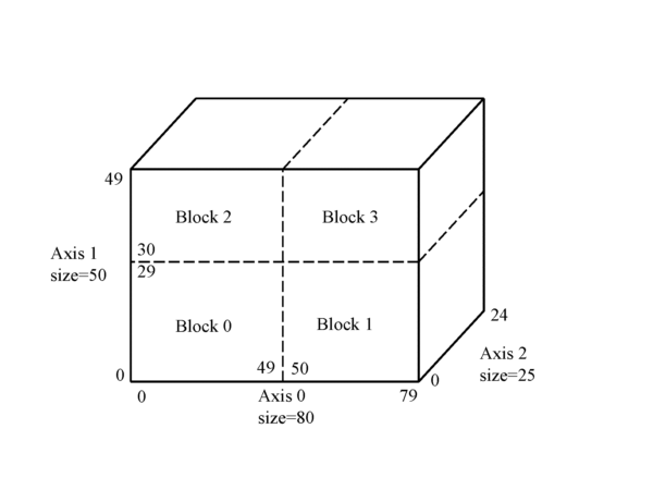
Figure 4.4 — Three-dimensional data table example
This data table instance has been partitioned into four data blocks with the subextents shown in Table 4.2:
Table 4.2 — Three-dimensional data table example subextents
|
|
Axis 0 |
Axis 1 |
Axis 2 |
block_data_value array |
|---|---|---|---|---|
|
Block 0 |
0, 49 |
0, 29 |
0, 24 |
(50,30,25) |
|
Block 1 |
50, 79 |
0, 29 |
0, 24 |
(30,30,25) |
|
Block 2 |
0, 49 |
30, 49 |
0, 24 |
(50,20,25) |
|
Block 3 |
50, 79 |
30, 49 |
0, 24 |
(30,20,25) |
The block_data_values in the n-dimensional array for a specific block are sequenced such that the values along the last axis are stored in order, followed by the values of the penultimate axis continuing until the values of the first axis have been stored.
For the three-dimensional table example above, the ith element in block_data_value is specified for each block by:
Block 0: (x ´ 30 ´ 25) + (y ´ 25) + z
Block 1: (x ´ 30 ´ 25) + (y ´ 25) + z
Block 2: (x ´ 20 ´ 25) + (y ´ 25) + z
Block 3: (x ´ 20 ´ 25) + (y ´ 25) + z
where (x,y,z) is the coordinate of the block_data_value in the three-dimensional array.
The element values within the DT_BLOCK_DATA object may be packed or not packed. If not packed, the block_data_values represent the actual element values and are encoded based on their data type. Encoding of data types is specified in 5 Encoding of data types.
For integer and float data types, the element values may be packed. In this case, the block_data_values are encoded as bit fields representing unsigned numbers and are used to calculate the element values. The size of these bit fields for a given block may vary depending on the data type and the element values in the block. These block_data_value bit fields are encoded one after another with no padding and without respect to any word boundaries. This is depicted in Figure 4.5 for four block_data_values with a bit field size of five represented by aaaaa, bbbbb, ccccc, and ddddd:
Figure 4.5 — Block_data_value five-bit fields
The DT_BLOCK_PARAM object (see 6.3.4.4 DT_BLOCK_PARAMS object) specifies the parameters needed to calculate the element values from the block_data_values. The packing parameters include a base_data_value, a scale_factor, a tolerance (for floating point values) and possibly a list of sentinel value mappings used to encode element values that represent metadata values in the DRM_Data_Table object.
The base_data_value packing parameter is of the same type as the element. For integer types, it is the minimum element value in the block. For floating point types, the base_data_value is the largest multiple of the tolerance that is less than the minimum element value.
The tolerance packing parameter is only used for floating point types. Element values are encoded as multiples of tolerance. The meaning of tolerance is the same as the EDCS_Value_Characteristic code EVC_TOLERANCE as specified in Table 6.33 of ISO/IEC 18025. Packing floating point data will necessarily result in a loss of precision for the element values that are being encoded. For this reason, if a tolerance is to be provided, it shall be specified in the transmittal in the DRM_Property_Characteristic component of the elements DRM_Table_Property_Description. If not specified, tolerance is undefined and floating point values are packed at full resolution.
These metadata values in the DRM are represented by DRM_Property_Characteristic components of the DRM_Table_Property_Description objects. The fields of a DRM_Property_Characteristic have an EDCS_Value_Characteristic code and a value representing a sentinel for that code.EXAMPLE Let the EDCS_Value_Characteristic code be EVC_MISSING with a corresponding sentinel value of -1. If a cell for an element has a value of -1, its meaning is that the cell data is missing for that cell.
Since sentinel values are usually values outside the normal range (e.g., -1 or 65535), it is more efficient to encode a mapped_sentinel value in the block_data_value bit field. The sentinel value mappings that are specified in the DT_DATA_PARAMS object define each sentinel value with its corresponding mapped value. It is the mapped value that is stored in the block_data_value bit field. Since these mapped sentinel values cannot correspond to values that yield actual element values, an extra bit may need to be allocated when determining the size of the bit field for the block_data_value. There is no requirement that the DRM_Property_Characteristic sentinel be given a mapped value. Specifying a mapped value increases the efficiency of the packing.
For integer types, the block_data_value is compared to each of the mapped_sentinel_values and, if found, the corresponding sentinel_value is used. If not found, element_value is computed as follows:
element_value = (block_data_value × 2scale_factor) + base_data_value
For floating point types, the block_data_value is first compared to the list of sentinels and, if not found, element_value is computed as follows:
element_value = (block_data_value × 2scale_factor) × tolerance + base_data_value
The concept of DRM_Property_Characteristic is described in 4.8.1.2.2 <DRM Property Characteristic> of Part 1 of ISO/IEC 18023.
http://www.iso.ch/iso/en/ittf/PubliclyAvailableStandards/ISO_IEC_18023-3_Ed1.html