4 Concepts
4.1 Introduction
The SRM provides an integrated framework and precise terminology for describing spatial concepts and operations on spatial information (including positions, directions, and distances). The SRM includes the following features:
a) precise and uniform definitions of commonly used spatial coordinate systems, including those based on map projections,
b) spatial referencing support for physical spatial objects, including artificial objects and non-terrestrial celestial bodies, as well as abstract spatial objects,
c) spatial operations on positions and directions, including coordinate conversions and transformations, and calculations of distances and other geometric quantities, along with an application program interface for performing these spatial operations,
d) codes and labels to support the encoding and exchange of spatial data,
e) an extensible framework that supports the registration of additional instances of SRM concepts, and
f) profiles to allow subsets of the SRM to be defined to conform to the specific requirements of an application or an application domain.
This International Standard is based on the following conceptual approach:
a) Spatial positions are identified by coordinates in a spatial coordinate system. The collection of spatial positions associated with a spatial object of interest, such as the Earth, is called its object-space (see 4.2).
b) A spatial reference frame specifies a spatial coordinate system by combining an abstract coordinate system with an object reference model. An abstract coordinate system may be combined with many different object reference models. Thus, a geodetic coordinate tied to the Earth object reference model WGS_1984 does not identify the same place as when tied to the Earth object reference model EUROPE_1950, or when tied to an object reference model for Mars (see 4.6.3 and Clause 8).
c) An abstract coordinate system associates coordinates with positions in an abstract Euclidean space, which is called its position-space. Abstract coordinate systems are defined independently of any object-space. There are many spatial spherical coordinate systems for a given object-space, but there is only one abstract spherical coordinate system for a position-space (see 4.6.1 and Clause 5).
d) An object reference model determines a precise relationship between position-space and the object-space for a spatial object of interest. Different object reference models for the Earth relate position-space to the object-space of the Earth in different ways. Thus, the object reference model WGS_1984 relates the position-space x-axis to the direction from the Earth’s center of mass towards the intersection of the Greenwich meridian with the equator, while the object reference model EARTH_INERTIAL_J2000r0 relates the position-space x-axis to the direction from the Earth’s center of mass towards the first point of Aries (see 4.5 and Clause 7).
e) The position-space to object-space relationship determined by an object reference model is expressed mathematically by a length-preserving embedding function called a normal embedding (see 4.3 and Clause 7).
f) A reference datum is a geometric primitive that relates measurements and/or geometric characteristics of object-space to position-space. Object reference models use reference datums to specify the position-space to object-space relationship. An object reference model may also use reference datums to model a geometric aspect of a spatial object. Thus, an oblate ellipsoid reference datum may be used to model the figure of the Earth or other celestial bodies (see 4.4 and Clause 7).
g) Temporal coordinate systems are introduced to describe the time-varying characteristics of spatial reference frames (see 4.6 and Clause 6).
h) Vertical offset surfaces are introduced to define heights with respect to equipotential or other complex surfaces. In particular, the vertical offset surface EGM96_GEOID represents the geopotential surface defined by the WGS 84 EGM 96 Earth Gravitational Model that is closely associated with the mean ocean surface (see 4.8 and Clause 9).
The relationships among some of these concepts are depicted in Figure 4.1. An abstract coordinate system is based on the underlying Euclidean structure of position-space. The reference datums that comprise the object reference model determine how position-space relates to object-space. That relationship is mathematically expressed by a normal embedding. A spatial reference frame combines the abstract coordinate system with the object reference model to specify a spatial coordinate system. This allows positions to be expressed relative to a spatial object of interest, such as the Earth.
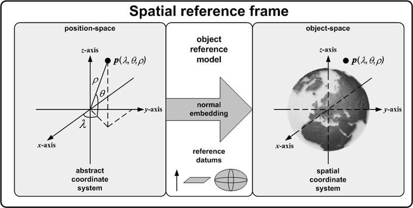
Figure 4.1 — SRM conceptual relationships
The concepts outlined in this sub-clause are discussed in greater detail in the remainder of this clause. This International Standard takes a functional approach to the definition of these concepts. Basic geometric concepts, including the concepts of point, line, and plane, are assumed. Annex A provides a concise summary of important specialized mathematical concepts and notational conventions used in this International Standard.
4.2 Spatial objects and object-space
Object-space is an abstract universe1 or a real universe that is associated with a designated spatial object of interest. Object-space is the context in which all spatial locations are represented and spatial operations are performed. A rigid spatial object is assumed to be fixed in its object-space (see Example 1).
The spatial objects of concern in this International Standard may be divided into two types: physical objects and abstract objects.
Physical objects are real world objects. The length of one metre has intrinsic meaning in the object-space of a physical object.
Abstract objects are conceptual objects including virtual, engineering, and/or mathematical models. A length of one metre does not have intrinsic meaning in the object-space of abstract objects. For the purpose of specifying relationships among abstract object-spaces, a designated length scale shall be associated with each abstract object-space.
A point in object-space may have a fixed location with respect to the spatial object. If points and objects have a time-dependent relationship, locations shall be qualified by a time value in a temporal coordinate system. Thus, at a specified time, the points and objects have a spatially-fixed relationship.
EXAMPLE 1 The Sun and the Earth are both physical objects, each with its own object-space. In the object-space of the Sun, the Sun is fixed and the Earth moves. In the object-space of the Earth, the Earth is fixed and the Sun moves.
EXAMPLE 2 At any given instant the International Space Station (ISS) has a location in the object-space of the Earth.
EXAMPLE 3 Each component of the ISS has a location in the object-space of the ISS.
EXAMPLE 4 A solar collector component of the ISS was manufactured in compliance with an engineering design. The CAD/CAM model that specifies the design for that component is defined in an abstract object-space.
4.3 Position-space and normal embeddings
Position-space is an n-dimensional Euclidean space, for n = 1, 2, or 3. Position-space serves as a vector space abstraction of object-space so that the methods of linear algebra and multivariate calculus may be applied to spatial concepts.
A normal embedding is a distance-preserving function from positions in position-space to points in object-space. The distance-preserving property requires that, whenever a pair of points in object-space corresponds via the normal embedding function to a pair of positions in position-space, the Euclidean distance between the pair of positions in position-space equals the distance in metres between the pair of object-space points. The distance-preserving property implies that a normal embedding is one-to-one and continuous. Normal embeddings also preserve other important geometric properties. Position-space together with a normal embedding is a specific algebraic model of object-space. In particular, normal embeddings are used to relate abstract coordinate systems in Euclidean space to spatial coordinate systems in object-space (see 4.6.3).
The origin of a normal embedding is the point in object-space associated by a normal embedding with the position-space origin. A normal embedding of a 3D position-space is right-handed if the triangle formed by the three points associated to the x-axis unit point, the y-axis unit point, and the z-axis unit point, in that order, has a clockwise orientation when viewed from the origin of the normal embedding. Otherwise, the normal embedding is left-handed. In this International Standard, all 3D normal embeddings shall be right-handed.
Algebraic models of an object-space are not unique. There are infinitely many normal embeddings of an n-dimensional position-space. Figure 4.2 illustrates two distinct normal embeddings. These normal embeddings provide two distinct algebraic models of the same object-space. Some dynamic applications require a continuum of normal embeddings parameterized by time.
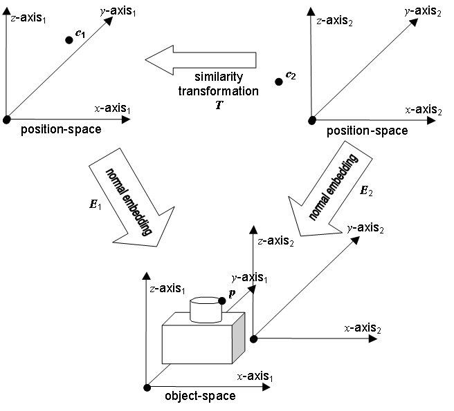
Figure 4.2 — Two position-space normal embeddings2
Any two normal embeddings for the same object-space can be inter-converted
with a transformation consisting of a
translation, a rotation and a scale factor. Such a transformation is called a similarity
transformation. If E1 and E2 are two normal embeddings, there
is a similarity transformation T such that E2 is the composition of E1 with T, ![]() This is depicted in Figure
4.2 where
This is depicted in Figure
4.2 where ![]() and
and![]() . The similarity
transformation is such that
. The similarity
transformation is such that ![]() so
that
so
that ![]() .
.
The method of specifying a normal embedding varies across disciplines and application domains. In the case of an abstract spatial object, the object-space is itself a Euclidean space and the identity function is an implicit normal embedding. In some application domains, a normal embedding is implicitly defined by the specification of the origin point and axis directions. In the case of geodesy, an origin point at the centre of the Earth cannot be directly specified. Instead, its location is implied by specifying other geometric entities from physical measurements. Other disciplines use a variety of techniques to either implicitly or explicitly define a normal embedding. This International Standard abstracts and encapsulates these techniques within the concepts of reference datum and object reference model.
4.4 Reference datums
A reference datum is a geometric primitive in position-space. Reference datums are points or directed curves in 2D position-space or points, directed curves or oriented surfaces in 3D position-space.
A reference datum is bound when the reference datum in position-space is identified with a corresponding constructed entity (i.e., a measured or conceptual geometric aspect of a spatial object) in object-space. The term “corresponding” in this context means that each position-space reference datum is bound to a constructed geometric entity of the same geometric object type. That is, position-space points are bound to object-space points, position-space lines to object-space lines, position-space curves to object-space curves, position-space planes to object-space planes, and position-space surfaces to object-space surfaces.
EXAMPLE 1 An ellipsoid reference datum with major semi-axis a and minor semi-axis b is the surface implicitly defined by:
![]()
and is illustrated in Figure 4.3.
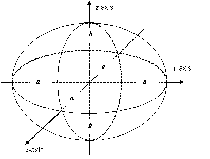
Figure 4.3 — An ellipsoid reference datum
Figure 4.4 illustrates two distinct bindings of a point reference datum. On the left, the point reference datum is bound to a specific point in the abstract object-space of a CAD/CAM model. On the right, the point reference datum is bound to a corresponding point in the physical object-space of an object that has been manufactured in accordance to that CAD/CAM model.
In some application domains, bound reference datums are used to model a significant aspect of the problem domain. In particular, in geodesy, oblate ellipsoids are used to model the figure of the Earth or a subset thereof.

Figure 4.4 — A reference datum bound to abstract and physical object-spaces
EXAMPLE 2 Semi-axis values a and b, ![]() are selected to specify an oblate ellipsoid reference datum. The
following steps (see Figure 4.5) illustrate one way to bind an ellipsoid reference datum specified
by semi-axis values a and b to a conceptual ellipsoid that represents the figure of the Earth in a region as
approximated by a geodetic survey control network:
are selected to specify an oblate ellipsoid reference datum. The
following steps (see Figure 4.5) illustrate one way to bind an ellipsoid reference datum specified
by semi-axis values a and b to a conceptual ellipsoid that represents the figure of the Earth in a region as
approximated by a geodetic survey control network:
a) A point on the surface of the reference datum is specified. This point has a computable geodetic latitude φ.
b) The specified position-space point is identified with a specific point in object-space.
c) The direction of the oblate ellipsoid rotational axis is constructed in object-space.
d) The direction of the outward surface normal at the point is
constructed in object-space so that the angle it makes with respect to the oblate
ellipsoid rotational axis direction is ![]() .
.
This binding requires the specification of a point and two directions in object-space.
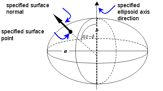
Figure 4.5 — A reference datum binding
This International Standard specifies a set of reference datums for use in subsequent specifications, including points, axis lines, planes, and ellipsoids. Additional reference datums may be defined by registration, as described in 4.13.
A reference datum may be associated with a corresponding constructed entity in object-space by means of a reference datum binding. The same reference datum may also be associated with a set of points in object-space by means of a normal embedding. The associated set in the latter case is the normal embedding functional image of the locus of points of the reference datum. These two means of association are not necessarily related, nor will the two sets of associated points in object-space be necessarily coincident or otherwise related.
A normal embedding of position-space and a reference datum binding are compatible if the normal embedding image of the reference datum primitive is coincident with the points (and direction or orientation, as applicable) of the constructed entity of the reference datum binding.
In general, a reference datum binding may be compatible with many different normal embeddings. Given a set of two or more bound reference datums, a single normal embedding that is compatible with each of the bindings may or may not exist. By properly combining multiple reference datum bindings, a unique compatible (right-handed in the 3D case) normal embedding may be specified.
EXAMPLE 3 The origin point reference datum is bound to a specific constructed point in object-space. The x-axis reference datum is bound to a specific constructed directed line in object-space. No compatible normal embedding exists unless the constructed point lies on the constructed directed line. If the point lies in the directed line, then there is exactly one compatible normal embedding in 1D position-space. In cases of 2D or 3D position-spaces, if the point lies on the directed line, there are infinitely many compatible normal embeddings.
4.5 Object reference models
An object reference model for a spatial object is a set of bound reference datums for which there exists exactly one (right-handed in the 3D case) normal embedding of position-space into object-space that is compatible with each reference datum binding in the set.
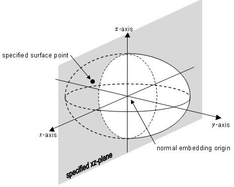
Figure 4.6 — An object reference model
EXAMPLE 1 An object reference model is constructed from three reference datums: an oblate ellipsoid reference datum (with specified parameter values a and b), a z-axis reference datum and an xz-plane reference datum.
a) The oblate ellipsoid reference datum is bound to a conceptual ellipsoid in object-space as in 4.4 Example 2 with major and minor semi-axis values a and b metres, respectively.
e) The z-axis conceptual line divides the xz-conceptual plane into two half-planes. One half-plane is designated as the x-positive half-plane. The intersection of the equatorial plane of the conceptual ellipsoid with this x-positive half-plane determines the x-axis of the spatial coordinate system and its direction. Since there is one and only one y-axis choice that is right-handed, a compatible normal embedding is uniquely determined by these three reference datum bindings (see Figure 4.6).
A binding constraint is a relationship in object-space between the constructed entities of two or more bound reference datums, or a size relationship between a reference datum primitive and its corresponding constructed entity. Binding constraints are formulated to ensure that there will exist at least one compatible normal embedding when the reference datums are bound.
EXAMPLE 2 The object reference model in 4.5 Example 1 includes the following three binding constraints:
a) The oblate ellipsoid reference datum is bound to a conceptual ellipsoid that has major semi-axis length of a metres and minor semi-axis length of b metres.
b) The z-axis reference datum is bound to an object-space conceptual line that coincides with the axis of rotation of the conceptual ellipsoid.
c) The xz-plane reference datum is bound to an object-space conceptual plane that contains the z-axis conceptual line.
Object reference models that have similar reference datums and that have the same binding constraints are abstracted in the notion of an object reference model template.
An object reference model template is a set of reference datums and binding constraints such that, whenever the reference datums in the set are bound in compliance with the set of binding constraints, then that bound set of reference datums form an object reference model. An object reference model template can be used to conveniently specify multiple object reference models.
EXAMPLE 3 Based on 4.5 Example 1, an object reference model template may be specified by the following set of three reference datums and set of three binding constraints. The reference datum set is:
a) An oblate ellipsoid with major semi-axis a and minor semi-axis b.
b) The z-axis.
c) The xz-plane.
The binding constraints are:
a) The object-space ellipsoid major semi-axis length shall be a metres and the minor semi-axis length shall be b metres.
b) The z-axis binding shall coincide with the axis of rotation of the ellipsoid.
c) The xz-plane binding shall contain the z-axis.
An object reference model is a realization of an object reference model template if the reference datums of the object reference model match the reference datum set of the object reference model template, and the reference datum bindings of the object reference model are compliant with its binding constraints.
EXAMPLE 4 The object reference model in 4.5 Example 1 is a realization of the object reference model template in 4.5 Example 3.
EXAMPLE 5 Object reference model European Datum 1950 (specified in Annex E as object reference model EUROPE_1950) is a realization of the object reference model template in 4.5 Example 3 using the International 1924 ellipsoid reference datum (specified in Annex D as reference datum INTERNATIONAL_1924.)
The object reference model template concept allows for a consistent method of specification for object reference models. This International Standard specifies a standard set of object reference model templates (see Clause 7). It also specifies a set of standard object reference models as object reference model template realizations (see Annex E).
4.6 Coordinate systems
4.6.1 Abstract coordinate systems
An abstract coordinate system is a means of identifying a set of positions in a position-space by coordinate n‑tuples. The space of these n‑tuples is called coordinate-space.
An abstract coordinate system is comprised of a domain, a range, and a generating function. The generating function is a smooth, one-to-one function from the domain in n-dimensional coordinate-space onto the range that is a set of positions in m-dimensional position-space (1 ≤ n ≤ m ≤ 3).
The generating function is often derived from geometric and trigonometric relationships as in Example 1. The generating function may be parameterized by coordinate system parameters.
The coordinate-space and position-space dimensions characterize an abstract coordinate system by coordinate system type as in Table 4.1.
Table 4.1 — Coordinate system types
|
Coordinate system type |
Dimension of coordinate-space |
Dimension of position-space |
|
3D |
3 |
3 |
|
surface |
2 |
3 |
|
curve |
1 |
3 |
|
2D |
2 |
2 |
|
plane curve |
1 |
2 |
|
1D |
1 |
1 |
The term “coordinate system”, if not otherwise qualified, means “abstract coordinate system.”
EXAMPLE 1 The polar
coordinate system is an example of an abstract coordinate system of coordinate
system type 2D that is defined with the generating function ![]() where
where ![]() and
and![]() . The domain of F in
coordinate-space is
. The domain of F in
coordinate-space is ![]() .
The range of F in position-space is
.
The range of F in position-space is ![]() The
geometric and trigonometric relationships for this generating function are
illustrated in Figure 4.7.
The
geometric and trigonometric relationships for this generating function are
illustrated in Figure 4.7.
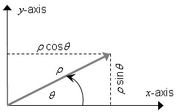
Figure 4.7 — The polar coordinate system geometric and trigonometric relationships
The polar coordinate system generating function F is illustrated in Figure 4.8. The grey boxes with lighter grey edges in this figure represent the fact that the range in position-space extends indefinitely, and that the domain in coordinate-space extends indefinitely along the r-axis. The dotted grey edges of the domain indicate an open boundary. There are no coordinate system parameters for this coordinate system.
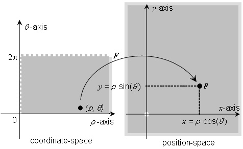
Figure 4.8 — The polar coordinate system generating function
EXAMPLE 2 The geodetic coordinate system for positions on the surface of an oblate ellipsoid is an example of a coordinate system of coordinate system type surface. The geometric and trigonometric relationships for the generating function of this coordinate system are illustrated in Figure 4.9. The generating function for this coordinate system depends on the major and minor semi-axis parameter values a and b. These are the coordinate system parameters. This coordinate system is fully specified in Clause 5 as the surface geodetic coordinate system.
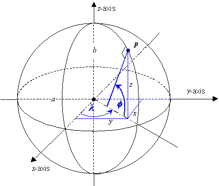
Figure 4.9 — The surface geodetic coordinate system geometric and trigonometric relationships
EXAMPLE 3 The geodetic coordinate system for positions in the space containing an oblate ellipsoid is an example of a coordinate system of coordinate system type 3D. The geometric and trigonometric relationships for the generating function of this coordinate system are illustrated in Figure 4.10. The coordinate system parameters are the major and minor semi-axis values a and b. This coordinate system is fully specified in Clause 5 as the geodetic coordinate system.
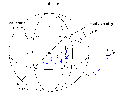
Figure 4.10 — The geodetic coordinate system geometric and trigonometric relationships
A coordinate system is a linear coordinate system if its generating function is an affine function.
EXAMPLE 4 The identity function on 3D Euclidean space is the generating function of the Euclidean 3D coordinate system. Both the coordinate system domain and range sets are the entire space. In this case, coordinate-space and position-space are one and the same. The Euclidean 3D coordinate system is a linear coordinate system.
Maps are traditionally created by projecting a region of the surface of an oblate ellipsoid (or sphere) onto a 2D surface for presentation and other user purposes. The functions that implement this projection are called mapping equations and are defined in terms of surface geodetic coordinates on the ellipsoid. When inverse mapping equations are composed with the surface geodetic coordinate system generating function, the resulting function is the generating function for a surface coordinate system. In this way, coordinate systems based on traditional map projections may be treated as a special case of abstract coordinate systems of coordinate system type surface. This special case is called a map projection coordinate system.
Note In other contexts, map projection coordinate systems are sometimes described as rectilinear or Cartesian because of the vector space structure of coordinate-space. That description does not imply that a map projection coordinate system is a linear coordinate system. Map projection coordinate systems are not linear because the associated generating functions are not affine. With respect to a linear coordinate system for the same position-space, map projection coordinate systems exhibit various types of distortion (see 5.8.3). In applications the effect of distortion is often mitigated by restricting the coordinate system domain of the map projection to a smaller sub-set.
4.6.2 Temporal coordinate systems
A temporal coordinate system is a means of associating a unique time with an event. It is an abstract coordinate system of coordinate system type 1D that is embedded into the time continuum by identifying the coordinate system origin with an epoch, a point in time identified by an event. Coordinated universal time is a temporal coordinate system that is described in Clause 6.
This International Standard uses the concept of time in several ways. Dynamic systems are treated as systems with a time parameter. These systems reduce to the case of a static relationship by fixing a value for the time parameter. Object reference model bindings are often based on physical measurements of objects or systems that change with time. Time is also used to identify the epoch for which these measurements are applicable.
4.6.3 Spatial coordinate systems
A spatial
coordinate system is a means of associating a
unique coordinate with a point in object-space. Abstract coordinate systems are
defined (above) for position-spaces. A position-space can serve as a model of
an object-space by specifying a normal embedding. Using this concept, a spatial
coordinate system is defined as a combination of an abstract coordinate system
and a normal embedding into the
object-space. The abstract coordinate system generating function G
associates coordinates in a coordinate-space to positions in position-space. A
normal embedding E maps those positions in position-space to points in object-space. If c is
a coordinate for the coordinate system, then c
identifies the object-space point ![]() as
illustrated in Figure 4.11.
as
illustrated in Figure 4.11.
EXAMPLE 1 The abstract Euclidean 3D coordinate system is composed with a normal embedding E1 of 3D position-space into an object-space to produce a spatial Euclidean 3D coordinate system. The abstract Euclidean 3D coordinate system is composed with a second distinct normal embedding E2 to produce a second spatial Euclidean 3D coordinate system. A point p on the object has a different Euclidean 3D coordinate in each of the two spatial coordinate systems. See Figure 4.12.
EXAMPLE 2 An engineering model is designed in abstract 3D Euclidean space using the Euclidean coordinate system. In this simple case, coordinate-space, position-space, and object-space are all identical (the generating function and normal embedding are both the identity operator). However, each of the spaces (coordinate, position, and object) is serving an implicit, but distinct, role.
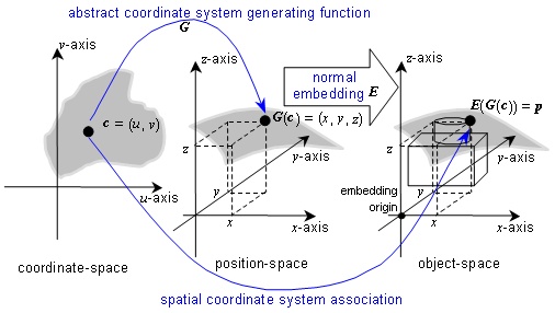
Figure 4.11 — A normal embedding of an abstract coordinate system
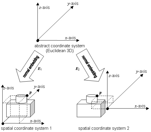
Figure 4.12 — Two spatial coordinate systems for the same object-space3
4.7 Spatial reference frames
A spatial reference frame is a means of specifying a spatial coordinate system for an object space. The spatial reference frame concept uses an object reference model to specify a normal embedding. That normal embedding combined with an abstract coordinate system comprises the spatial coordinate system (see 4.6.3).
A spatial reference frame for a spatial object is comprised of:
a) an object reference model for the spatial object;
b) an abstract coordinate system;
c) a binding of the abstract coordinate system parameters, if any, to specific values; and
d) (optionally) other names and/or symbols for coordinate-components.
The binding of the coordinate system parameters is often related to characteristics of the reference datum components of the object reference model used. Spatial reference frames and the mechanisms to create them are normatively defined in Clause 8. A spatial reference frame specification may include a designation of a valid region that is a subset of the coordinate system domain. Acceptable uses of valid regions are specified in 8.3.2.4.
A spatial reference frame template is an abstraction of a set of spatial reference frames that share the same abstract coordinate system, coordinate system parameter binding rules, and coordinate-component names and symbols. The coordinate system parameter binding rules may depend on both the characteristics of the reference datums in the object reference model and the manner in which the reference datums are bound in the object-space. Therefore, a spatial reference frame template specification includes the type of spatial object and constraints on the set of object reference models for the spatial object.
A spatial reference frame template is comprised of the following items:
a) a spatial object type constraint,
b) object reference model constraints,
c) an abstract coordinate system,
d) coordinate system parameter binding rules, and
e) (optionally) other names and/or symbols for coordinate-components.
The spatial reference frame template concept is normatively defined in Clause 8.
EXAMPLE 1 The celestiodetic spatial reference frame template consists of the following specifications:
a) the object type is a physical object,
b) the object reference model is a realization of the oblate ellipsoid object reference model template,
c) the abstract coordinate system is the geodetic coordinate system (see Table 5.24), and
d) the major and minor semi-axis coordinate system parameter values, a and b, are equal to the major and minor semi-axis values of the oblate ellipsoid reference datum of the ellipsoid object reference model.
A spatial reference frame for an object is said to be derived from a given spatial reference frame template if it is compliant with that spatial reference frame template specification. The spatial reference frame template concept allows for a consistent method of specification for spatial reference frames. In this International Standard, each spatial reference frame is derived from a spatial reference frame template that is specified in Clause 8.
EXAMPLE 2 The Geodetic WGS 1984 spatial reference frame may be derived from the template in Example 1 by specifying the Earth as the spatial object and WGS_1984 as the object reference model.
EXAMPLE 3 A different geodetic spatial reference frame may be derived from the template in Example 1 by specifying the Earth as the spatial object and EUROPE_1950 (see 4.5 Example 5) as the object reference model. This spatial reference frame and the spatial reference frame in Example 2 both use the geodetic coordinate system but they are distinct spatial reference frames. In general, they assign different coordinates to each point in the object-space of the Earth.
It is often the case, particularly with map projection coordinate systems, that one spatial reference frame cannot cover a large area within the limits of allowable distortion. A spatial reference frame set for a spatial object is a finite parameterized set of two or more spatial reference frames that:
a) use the same object reference model for the spatial object,
b) are derived from the same spatial reference frame template, and
c) the valid regions of the set members have non-overlapping interiors.
The specification of a spatial reference frame set may add restrictions to the object reference model constraints of the specified spatial reference frame template. The spatial reference frame set concept is specified in Clause 8 .
EXAMPLE 4 The Universal Transverse Mercator system is an example of a spatial reference frame set.
4.8 Designated spatial surfaces and vertical offsets
Many spatial applications require the specification of surfaces in object-space that are more complex than a surface reference datum. These surfaces often represent some conceptual or physical aspect of the object-space such as a gravity equipotential surface. Such surfaces are termed designated spatial surfaces. In particular, a model of the geoid is a designated spatial surface.
For spatial reference frames that have a vertical coordinate-component, certain designated spatial surfaces may be used to define vertical offset values. Many real-world measurement systems used in geodesy define the value of the vertical coordinate-component of a spatial reference frame to be zero at a designated spatial surface. If the point of intersection between each vertical coordinate-component curve and the designated spatial surface is unique, that point specifies a vertical offset value, and the designated spatial surface is termed a vertical offset surface for the given spatial reference frame.
Figure 4.13 illustrates a vertical offset surface in a case where the vertical coordinate-component is ellipsoidal height h. The vertical offset v at a point p is the distance from the ellipsoid reference datum surface to the vertical offset surface along the ellipsoidal height coordinate curve that contains p. The vertical offset v = v(λ,φ) depends only on the point of intersection of the ellipsoid surface and the ellipsoidal height curve. A model of the geoid is a vertical offset surface relative to ellipsoidal height. In that case, the elevation he of a point p with respect to the vertical offset surface is defined to be he = h – v(λ,φ).
A collection of designated spatial surfaces that are vertical offset surfaces with respect to a vertical coordinate-component of ellipsoidal height are specified in Clause 9. Although distances from vertical offset surfaces are not allowed as coordinate elements, the API (Clause 11) provides a method for vertical offset computation with respect to ellipsoidal height, if the surface can be modelled with a smooth surface generating function.
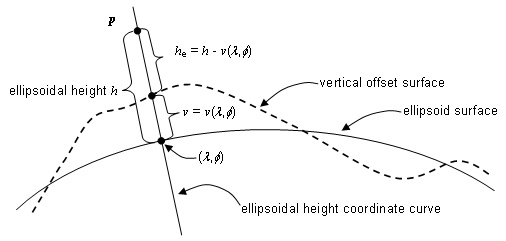
Figure 4.13 — A vertical offset surface for ellipsoidal height
4.9 Spatial reference frame operations
Different spatial reference frames may be specified for the same spatial object. A spatial reference frame operation re-expresses coordinates, directions, and/or distances expressed in one spatial reference frame in terms of a different spatial reference frame, or computes a distance or other geometric quantity within a single spatial reference frame. Clause 10 defines a number of standard spatial reference frame operations.
If SRFS and SRFT are two spatial reference frames
for a spatial object and if p is a position in the
object-space, it has coordinate ![]() in SRFT
and coordinate
in SRFT
and coordinate![]() in SRFS.
Computing the coordinate-component values of
in SRFS.
Computing the coordinate-component values of ![]() from those
of
from those
of![]() is
an instance of spatial reference frame operation. The computation in its most
general form is given by
is
an instance of spatial reference frame operation. The computation in its most
general form is given by![]() where
where
![]() and
and![]() are the coordinate
system generating functions and
are the coordinate
system generating functions and![]() is
a similarity transformation between the object reference models for SRFS
and SRFT. This is illustrated in Figure 4.14. Similar
mathematics are used to specify other spatial reference frame operations.
is
a similarity transformation between the object reference models for SRFS
and SRFT. This is illustrated in Figure 4.14. Similar
mathematics are used to specify other spatial reference frame operations.
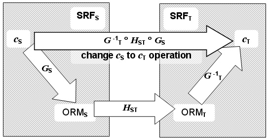
Figure 4.14 — Change of SRF representation
4.10 Application program interface
Clause 11 specifies data types for representing spatial information based on concepts in the SRM. It also specifies an extensible object-oriented application program interface that can be used to implement the spatial reference frame operations defined in this International Standard. The data objects and functional methods in this interface are based on the methods and spatial reference frame operations specified in Clauses 5, 9, and 10.
4.11 SRM units
In this International Standard, when specifying spatial reference frame operations, or as part of applications or exchange formats, the unit of length is the metre and the unit of angular measure is the radian. Some SRM parameter values are specified in either arc degrees or arc seconds to support common usages. Other equivalent units of measure may be used within an application or exchange format only if those units are identified. Whenever possible, such units shall be identified using the appropriate code as specified in Clause 7 of ISO/IEC 18025 [ISO/IEC18025]. Otherwise, the units shall be defined in terms of the metre or radian, as appropriate. When interfacing with the SRM API, the length and angular measurement units used shall be as specified in this International Standard. An implementation of the SRM API shall convert all length and angular measurements to metres and radians in spatial reference frame operations. When measures of computational accuracy are being determined, such computations shall use units of metres and radians where applicable.
4.12 Profiles
A profile is a subset of the SRM that is tailored to meet the needs of a specific application area (see Clause 12). The “default” profile is specified in 12.3. Only those subsets of the SRM that can define, represent and/or process spatial positions shall be allowed. Conformance of functional implementations and exchange formats are defined in the context of a profile (see Clause 14).
4.13 Registration
This International Standard specifies standardized instances of several SRM concepts. This International Standard allows new instances of some SRM concepts to be specified by registration (see Clause 13). These new instances are termed registered items
EXAMPLE The set of reference datums includes the standardized instance reference datum CLARKE_1866 and the set of object reference models includes the standardized instance object reference model WGS_1984.
New instances of the following SRM concepts may be registered:
a) abstract coordinate systems (see 5.9),
b) temporal coordinate systems (see Clause 6),
c) reference datums (see 7.2),
d) object reference model templates (see 7.4.4),
e) object reference models (see 7.4.5),
f) reference transformations (see 7.4.5),
g) object binding rule sets (see 7.5),
h) spatial reference frame templates (see 8.5),
i) spatial reference frames (see 8.6),
j) spatial reference frame sets and their members (see 8.7),
k) designated spatial surfaces (see Clause 9), and
l) profiles (see Clause 12).
New items are registered using the established procedures of the ISO International Registration Authority for Graphical Items 4. These procedures require the submitter to supply all information for a new SRM registered item. Registration shall be according to the procedures in ISO/IEC 9973. The guidelines that shall be followed in preparing registration proposals are specified in Clause 13. The specifications of all registered items include labels, codes, descriptions, and references, as well as other item-dependent information as required in this International Standard. Annex H provides a set of templates that may be used in the registration process.
Registration shall not be used to modify any existing standardized or SRM registered item (see Annex G for details concerning how standardized and registered items may be deprecated). Deprecated items, if any, are listed in Annex J.
Other International Standards that normatively reference this International Standard, implementations of those standards, and implementations of this International Standard shall not use any SRM registered item codes in the value ranges reserved for registration or future standardization by this International Standard with any meaning other than the one defined in this International Standard or in the International Register of Graphical Items.