An instance of this DRM class specifies a unit vector, the
meaning of which is specified by its
vector_type field.
Consider a <Polygon> instance specified in a 3D LSR SRF
for which a data provider wishes to explicitly provide the
surface normal vector so that consumers do not need to calculate
the surface normal when consuming that particular
<Polygon> instance.
The data provider specifies this vector information as a
<Reference Vector> component
of the <Polygon> instance as depicted in
Figure 55:
Figure 55 — <DRM Reference Vector> surface normal example
Since the <Reference Vector> instance
is a component of a <Polygon> instance, it
specifies an <LSR 3D Location>
component in order to comply with
<<Required Reference Vector Location>>.
Consider a <Reference Vector> instance, contained by a
<Polygon> instance, representing a normal vector that is used
for rendering purposes (that is, to calculate colour and shading when
rendering the <Polygon> instance). This
<Reference Vector> instance has a
vector_type of
SE_REFVEC_RENDERING_NORMAL.
Consider a <Polygon> instance F
classified as ECC_FENCE, where F is a
quadrilateral. F is instanced on some
terrain representation, such that the plane of F
is perpendicular to the surrounding terrain.
F has radar cross sections that are dependent
on aspect angles (azimuth and elevation). These aspect angles are
defined with respect to F's normal vector and
F's azimuth vector. Consequently,
F has two <Reference Vector>
components as depicted in
Figure 56:
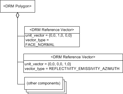
Figure 56 — <DRM Reference Vector> radar cross section example
The SE_REFVEC_FACE_NORMAL
<Reference Vector> component is the unit vector that is
perpendicular to the plane of F and points away
from F on its outside face. The azimuth
<Reference Vector> component is the unit vector that lies
in the plane of F and points straight up.
A segment of the road has a retroreflector (a device that reflects emissions
back along the incident path irrespective of its angle of incidence)
on it and is modelled as a <Line> instance. The
<Line> instance has a normal vector that is
perpendicular to it and an azimuth reference parallel to it. This is
sufficient to describe radar cross sections of the road as a function of
aspect angles. However, the normal vector for the infrared bands depends
on the orientation of the retroreflector, not the road. This is because
radars see the road but infrared see the retroreflector. In this example,
the <Line> instance has
four <Reference Vector> components
(radar-normal, radar-azimuth, infrared-normal, and infrared-azimuth).
A normal vector used for reflectivity/emissivity calculations is
represented by a <Reference Vector>
instance with vector_type =
SE_REFVEC_REFLECTIVITY_EMISSIVITY_NORMAL.
A vector specifying the direction of illumination of
an <Infinite Light> instance
is represented by a <Reference Vector>
component with vector_type =
SE_REFVEC_LIGHT_DIRECTION.
-
Why does
SE_Reference_Vector_Type
have so many entries
that appear to be mathematically similar, such as the
several different varieties of normal?
In the general case, a location on an environmental object
may have distinct vectors for each of these
SE_Reference_Vector_Type
entries, although in specific instances such vectors may coincide
with one another.
For example, consider a large flat window, represented
by a <Polygon> instance. The geometric normal
(SE_REFVEC_FACE_NORMAL)
in this example coincides with the radar
SE_REFVEC_EMISSIVITY_NORMAL
and with the infrared
SE_REFVEC_EMISSIVITY_NORMAL.
However, consider a more complex geometric representation -
in this example, a representation of an aircraft. Here the
SE_REFVEC_FACE_NORMAL
is not applicable, and the radar and infrared
SE_REFVEC_EMISSIVITY_NORMAL
<Reference Vector> instances do not coincide.
-
Why can a <Vertex> instance have only one
<Reference Vector> component,
when a <Primitive Geometry> instance
can have more than one?
A <Vertex> instance, unlike a
<Primitive Geometry> instance
such as a <Point> instance,
does not represent an environmental object, but only part of
an environmental object.
Examples:
A ship may be represented by a <Point> instance
S. The fact that S
represents an environmental object is indicated by providing
S with an appropriate
<Classification Data> component.
An environental object classified as ECC_EXTERNAL_WALL within
another environmental object classified as ECC_BUILDING
may be represented by a <Polygon> instance
W, but the individual <Vertex>
components of W do not themselves
represent environmental objects.
An environental object classified as ECC_BRIDGE may be
represented by a <Line> instance B,
but the individual <Vertex> components of
B do not themselves represent
environmental objects.
To fully describe aspect dependent characteristics as part
of the representation of an environmental object, the
representation requires at least two
<Reference Vector> components, one specifying a
normal and the other an azimuth.
In addition, a representation of
an environmental object may need to represent a combination
of geometric and/or sensor-related vectors simultaneously.
Since a <Vertex> instance does not itself
constitute a representation of an environmental object, it
does not require the capability of specifying multiple
<Reference Vector> components.
However, a <Vertex> instance may need a
SE_REFVEC_RENDERING_NORMAL
<Reference Vector> component
for use in smooth shading, so a single
<Reference Vector> component
may be needed for a given <Vertex> instance.
-
Why does a <Reference Vector>
instance have an optional <Location> component,
and if the <Location> component
is needed to support functionality, why is it optional?
The SEDRIS API provides the capability of converting
<Reference Vector> instances
between SRFs. These SRFs include non-vector space coordinates,
such as CD. To support those cases, a
<Reference Vector> instance
requires the ability to specify a
<Location> component.
However, in most contexts where a
<Reference Vector> instance can appear
in a transmittal, the
<Reference Vector> instance
inherits the appropriate <Location>
component from its context, and does not require a
direct <Location> component. See
<<Required Reference Vector Location>>
for the cases where an appropriate <Location> instance
cannot be inherited, so that
the data provider is required to specify such a component
directly for the <Reference Vector>
instance.