Definition
The number of <Image Mapping Function> instances referenced by
a <Geometry Representation> instance shall
equal the number of <Texture Coordinate>
components for each <Vertex> instance and
<Tack Point> instance within the
component tree rooted at that
<Geometry Representation> instance.
<Image Mapping Function> instances
referenced by <Feature Representation> instances,
on the other hand, shall either have <Image Anchor> components, or
reference <Image> instances that have
<Image Anchor> components.
EXCEPTION:
If an <Image Mapping Function>
instance is used to specify a non-planar projection (such as spherical,
cylindrical), it shall use
an <Image Anchor> component, and the
<Geometry Representation> instance
to which the
<Image Mapping Function> instance
is attached cannot have
<Texture Coordinate> instances or
<Tack Point> instances within its component tree.
Rationale
The multiple <Image Mapping Function>
instances and multiple
<Texture Coordinate> instances
are ordered, and are defined to correspond to each other as if they were in
parallel arrays.
<Image Mapping Function> instances
referenced by a <Feature Representation>
instance are attributes for geometry that is to be
derived by the consumer for the
<Feature Representation> instance. Since
<Texture Coordinate> instances and
<Tack Point> instances are not applicable to
<Feature Representation> instances, such
<Image Mapping Function> instances
shall be specified with <Image Anchor>
components.
Example
Consider a triangular <Polygon> instance with one
<Image Mapping Function> instance
for the OTW domain as shown in Figure 1.
Each of the three <Vertex> components of the
<Polygon> instance has one
<Texture Coordinate> component,
specifying the (s,t) within the image space
that will be mapped to that <Vertex> instance.
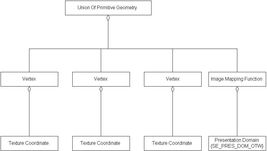
Figure 1 — <DRM Image Mapping Functions and Texture Coordinates> example1
Consider a triangular <Polygon> instance that has
different texture maps, one for OTW and one for thermal, as
shown in Figure 2.
The <Polygon> instance thus has two ordered
<Image Mapping Function> components,
so each of its <Vertex> components will have two ordered
<Texture Coordinate> components, one for
each <Image Mapping Function> instance.
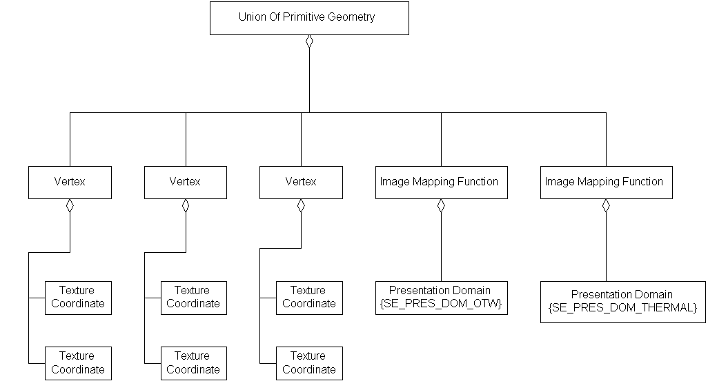
Figure 2 — <DRM Image Mapping Functions and Texture Coordinates> example2
FAQs
No FAQs supplied.
Prev: Image Anchor SRF.
Next: Index Codes within Tables.
Up:Index.