Class Name: Image Mapping Function
Subclasses
This DRM class is concrete and has no subclasses.
Definition
An instance of this DRM class specifies how the given <Image>
instance is to be mapped onto a given textured object,
including the mapping method, the projection, and how
<Texture Coordinate> instances
(if present) are to be treated if they fall outside the image space
bounded by the image indexes (0, 0) and (1, 1).
Primary Page in DRM Diagram:
Secondary Pages in DRM Diagram:
Example
Consider the visualization of a tree. An image of a tree stored
in an <Image> instance is to be mapped onto a rectangular polygon
represented by a <Polygon> instance as depicted in
Figure 25.
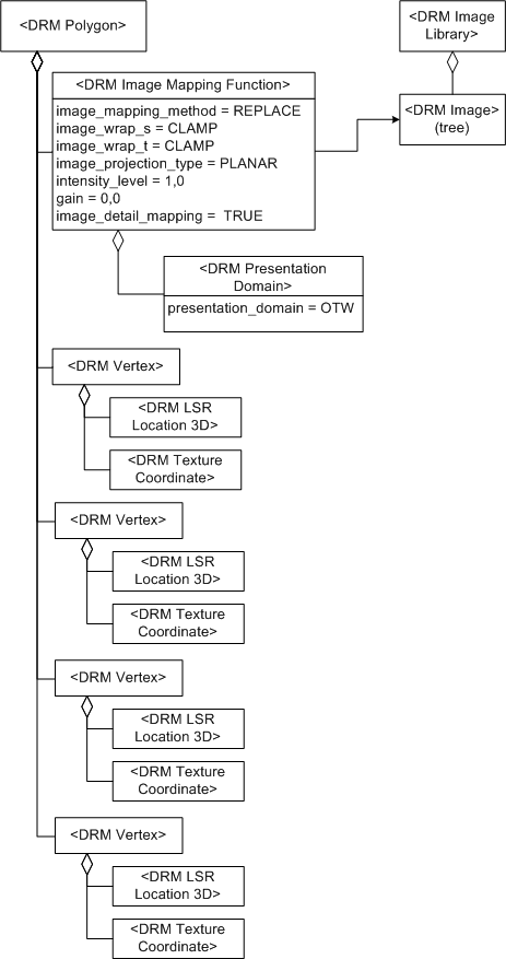
Figure 25 — <DRM Image Mapping Function> example
The <Polygon> instance is composed of:
an <Image Mapping Function> component associated to the
<Image> instance containing the tree data, and composed of
a <Presentation Domain> component with
presentation_domain
= {OTW}.
The fields of the <Image Mapping Function> instance are
specified as follows:
four <Vertex> components, where each <Vertex> component
is composed of:
-
An <LSR 3D Location> component specifying the location
coordinate of the <Vertex> instance, and
-
A <Texture Coordinate> component specifying the
texture coordinate of the vertex onto the texture map.
The texture coordinate values for each vertex map to
the [0.0, 0.0],
[1.0, 1.0] range of
texture coordinate space.
Consider a <Polygon> instance with two
<Image Mapping Function> components. One
<Image Mapping Function> component specifies the
<Image> instance displayed for most cases. The second
<Image Mapping Function> component, if
instance, if image_detail_mapping
is SE_TRUE, specifies the imagery that is added to
the <Polygon> instance when the eyepoint is so close
to the <Polygon> instance that the main <Image>
instance texels are no longer useful for texturing the
<Polygon> instance.
Considering <Polygon> instance D
representing the door of a truck that is painted brown, where
the door has a forestry service logo on it. D
has an <Inline Colour> component that colours the
polygon brown and an <Image Mapping Function> component
F that texture maps the logo onto the surface
of the door representation as follows.
F has
image_mapping_method =
SE_IMAGMAPMETH_DECAL.
The logo image has SE_IMAGSIG_123COLOUR_ALPHA
signature. The logo portion of the image has alpha = 1, the border of the
logo has alpha =
0.5, and the background of the image outside
the logo has alpha = 0.0. When
F is applied to the surface of
D, therefore, the logo replaces the
brown colour since it has alpha = 1, the background of the logo
is replaced by the brown colour since it has alpha = 0, and
the border of the logo blends the logo colour with the
brown colour since it has alpha = 0.5.
FAQs
-
What is the order of precedence for mapping
an <Image> instance to a geometric object, such as a
<Polygon> instance?
The <Texture Coordinate> instances
on the attribute geometry always have the highest precedence. Next,
if the attribute geometry has
<Tack Point> instances, three conditions
could occur.
If there is only one <Tack Point>, the
<Tack Point> is used to locate the imagery,
and the scaling and rotation information from the
<Image Mapping Function> is used.
If two <Tack Point> instances are defined,
the location and rotation of the imagery is taken from the
<Tack Point> instances, but the scaling
information is derived from the
<Image Mapping Function>.
If there are three or more <Tack Point>
instances, the position, rotation information is derived from the first
three <Tack Point> instances. Since
<Tack Point> components are unordered,
the complete set of supplied <Tack Point>
components shall define an orthogonal image
projection. This is to insure that no matter which three
<Tack Point> components are used, the same
projection is derived for the imagery.
If the <Polygon> does not have
<Texture Coordinate> or
<Tack Point> components,
then any <Image Anchor> components of the
<Image Mapping Function> define the
location of the image on the attribute geometry. If none of the previous
conditions are met, then the <Image Anchor>s in
the <Image> are used. If there are no
<Texture Coordinate>s, no
<Tack Point>s, no
<Image Anchor>s in the
<Image Mapping Function>
and no anchor points in the
<Image>, then the image mapping is undefined. It
should be noted that the final two cases can be
used to create non-orthogonal projections.
-
How can a non-orthogonal projection of texture be
created onto a textured object, e.g., a <Polygon>?
Since all texture mappings that are a result of texture coordinate
mapping at the polygon level are defined to be orthogonal projections,
a non-orthogonal projection cannot be created with
<Texture Coordinate> instances.
To create a non-orthogonal projection, the
<Image Anchor> components
shall be used. These points are defined in the
currently scoped SRF,
and therefore are not required to be in the plane of the
<Polygon> instance. There
is no method to create a non-orthogonal projection in
the local SRF of the <Model> instance.
-
Consider a data provider with a texture map that is applied to a textured
object using a spherical projection. How are the centre and
radius of projection stored in the
<Image Mapping Function> instance?
Rather than using <Texture Coordinate> instances to tie the
<Image Mapping Function> instance to the textured object,
use an <Image Anchor> instance. For a spherical projection,
the <Location> components of the
<Image Anchor> instance are interpreted as follows:
- origin (the centre of the sphere)
- direction (point on the north pole of the sphere)
- alignment (point at the equator of the sphere)
-
Given an <Image> that is to be applied to a
given object using a cylindrical projection, how can
an <Image Mapping Function> instance be
used to store the centre of projection?
The <Image Mapping Function> instance
for this case specifies an <Image Anchor> component,
while the object to be textured does not specify
<Texture Coordinate> instances. For
details of how the <Image Anchor>
instance specifies the cylindrical projection,
see the <Image Anchor> class.
-
When <Image Anchor> instances are used,
how are the rotation and scale of the image mapping represented?
The rotation and scale of the image mapping can be derived from the
<Location> instances representing the 3 corners
of the <Image> instance, i.e., the
<Location> components of the
<Image Anchor> instance.
-
When blending, how do is a blend (luminance) value interpreted?
1.0 = 100% Primary colour, No Blend contribution
0.0 = no Primary contribution, %100 Blend Colour
-
Does an <Image Mapping Function>
apply to both sides of a <Polygon>, or only the
front side? What if a data provider wants to represent a wall with
brick texture on one side and wallpaper texture on the other?
An <Image Mapping Function>
instance applies only to the front side of a
<Primitive Geometry>. In the wall
example, two <Polygon> instances are needed,
one with brick texture on its front side, facing the outside of the
building, and the other with wallpaper, facing the inside of the
building.
Any other representation would be lost in a rendering
system that used back-face culling.
Constraints
Associated to (one-way)
Composed of (two-way)
Component of (two-way)
Inherited Field Elements
This class has no inherited field elements.
Notes
Fields Notes
The image_mapping_method
field specifies how to combine the
referenced texture map with any <Colour>
instances on the textured object.
The image_wrap_s
field specifies whether to clamp or repeat
the given <Image> instance in s.
The image_wrap_t
field specifies whether to clamp or repeat
the given <Image> instance in t.
The image_projection_type
field specifies the type of projection
to be used when applying the given <Image>
instance to textured objects.
If planar projection is specified, the following cases may apply.
-
The DRM object may have
<Texture Coordinate> instances or
<Tack Point> instances, in which case
<<Image Mapping Functions and Texture Coordinates>>
applies.
-
The <Image Mapping Function>
instance may have
an <Image Anchor> component.
-
The <Image> instance may have
an <Image Anchor> component.
If cylindrical or spherical projection is specified, the DRM object
shall not have <Texture Coordinate> instances or
<Tack Point> instances. Instead, either the
<Image Mapping Function> instance or its
<Image> instance shall have
an <Image Anchor> component.
The intensity_level field specifies
the percent contribution of the <Image Mapping Function>
instance to the total effect on the textured object. For
an <Image> instance with a colour coordinate component
specified by its signature, multiply first, second, and third colour
coordinate values within the texels of the <Image>
instance by this value.
The value of the gain
field is to be added to each colour data
value from the texel data of the given <Image>
instance to obtain the displayed image.
The image_detail_mapping field
specifies whether the
<Image Mapping Function> instance
is used to describe mapping of a detail image on the
textured object.
Prev: Image Library.
Next: In Out.
Up:Index.